


CANBed - Arduino CAN-BUS Development Kit embeds an ATmega32U4 chip, which means you don’t need to add other jump wires to another Arduino Board, it is an Arduino board itself plus MCP2515 CAN Bus controller and MCP2551 CAN Bus transceiver!
Features
- Enhanced MCU Performance: ATmega32U4 with Arduino Leonardo bootloader on the board
- Compatible with Arduino: Combines CAN-BUS shield and Arduino development board together on a single board
- High Speed: Implements CAN V2.0B at up to 1 Mb/s
- Rich Resources in Pins: 18 pins that include digital pins, analog pins, UART, and I2C interface
- Easy to Use: Requires no other MCU to control and is compatible with Arduino IDE
CAN-BUS is a common protocol and widely used in industry due to its long travel distance, medium communication speed, and high reliability. Now you can realize a CAN-BUS project through this tiny little development board.
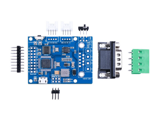
Because of the ATmega32U4 onboard chip, this board has rich resources in pins. As a matter of fact, there are 18 pins based on the core chipset up on the board, which include digital pins, analog pins, UART, and an I2C interface. Besides, this CANBed adopts the MCP2515 CAN Bus controller with SPI interface and MCP2551 to achieve the CAN-Bus capability. There are also two kinds of CAN Bus interfaces for various demands which are sub-D9 connector and terminal block interface. They would fit all your needs in the connecting method.
This CAN-Bus development board is perfectly compatible with Arduino IDE. With the help of the Arduino CAN-Bus library, you will save plenty of time for your CAN project.
What is CAN-BUS?
CAN stands for Controller Area Network, it is used to allow microcontrollers and devices to communicate with each other within a vehicle without a host computer which allows for control and data acquisition. These devices are also called Electronic Control Units (ECU) and they enable communication between all parts of a vehicle.
Today, you can find up to 70 ECUs in a modern car. CAN is a serial communication bus designed for industrial and automotive applications. For example, they are found in vehicles, farming equipment, industrial environments, etc.
How does CAN-BUS work?
The fuel level, door sensors, odometer, and many more parts of a car have to communicate with each other somehow, and CAN BUS is what they used to do. These CAN-compatible components, which are called “nodes” are connected with a 3-string copper wire, with no central router to govern the flow of data. Every node can hear the messages of every other node.
Every node has an ID, where the ones with the higher priority ID can have the priority to “talk” first while the others “listen”. This is to ensure that there are never two nodes talking at the same time. The biggest benefit of CAN-BUS is to be able to just connect components without having to worry about signal routing.
Learn more about CAN-BUS here.

Application
- Car hacking: The user can connect the circuit board to the OBD interface through the sub-D connector to read the data of the car
- Easy building prototype: ATmega32U4 chip leads out various additional functions which help especially beginners build various prototypes.
Specification
| Parameter | Value |
|---|---|
| MCU | ATmega32U4(with Arduino Leonardo bootloader) |
| Clock Speed | 16MHz |
| Flash Memory | 32KB |
| SRAM | 2.5KB |
| EEPROM | 1KB |
| Operate Voltage(CAN-BUS) | 9-28V |
| Operate Voltage (MicroUSB) | 5V |
| Input Interface | sub-D |
Hardware Overview

D-Sub CANbus PinOut
| pin# | Signal names | Signal Description |
|---|---|---|
| 1 | Reserved | Upgrade Path |
| 2 | CAN_L | Dominant Low |
| 3 | CAN_GND | Ground |
| 4 | Reserved | Upgrade Path |
| 5 | CAN_SHLD | Shield, Optional |
| 6 | GND | Ground, Optional |
| 7 | CAN_H | Dominant High |
| 8 | Reserved | Upgrade Path |
| 9 | CAN_V+ | Power, Optional |
Switch for the 120Ω terminal resistor for CAN Bus

If you use this slaver at the end of the CAN bus, you need to solder a 120Ω resister between the two pads, if not just leave them alone.
CAN Bus Family in Seeed

CAN-BUS series product selection reference is provided here. The table compares NEW-Release LoRa-E5 CAN, CANBed v1, CANBed FD, CANBed M4, and CANBed RP2040 in terms of MCU, protocol, memory, interface, etc.
|
Items |
CANBed v1 |
|||||
|
MCU |
Wio-E5 (STM32WLE5JC) |
ATmega32U4(with Arduino Leonardo bootloader) |
ATmega 32U4 (with Arduino Leonardo bootloader) |
ATSAME51 32bit Cortex M4 core |
RP2040 |
RP2040 (Dual ARM Cortex-M0+) |
|
Clock Speed |
up to 48MHz |
16MHz |
16MHz |
120MHz |
up to 133 MHz |
133MHz |
|
Protocol |
Long Range,RS485,CANFD & CAN2.0 |
CAN2.0 |
CANFD & CAN2.0 |
CANFD & CAN2.0 |
CAN2.0 |
CANFD & CAN2.0 |
|
Flash Memory |
256KB |
32KB |
32KB |
512KB |
2MB |
2MB |
|
SRAM |
64KB |
2.5KB |
2.5KB |
192KB |
264KB |
264KB |
|
EEPROM |
- |
1KB |
1KB |
- |
- |
|
|
Operate Voltage(CAN-BUS) |
4.5~28V |
9-28V |
7-28V |
7~28V |
9-28V |
9-28V |
|
Operate Voltage (MicroUSB) |
5V |
5V |
5V |
5V |
3.3V |
5V |
|
Lipo Battery |
3.7V |
- |
- |
- |
- |
- |
|
Input Interface |
9 pin sub-D or 4PIN Terminal |
9 pin sub-D or 4PIN Terminal |
sub-D or 4PIN Terminal |
sub-D as well as Terminal |
sub-D |
Sub-D |
|
Price |
$39.90 |
$24.90 |
$17.90 |
$19.90 |
$15.90 |
$14.9 |
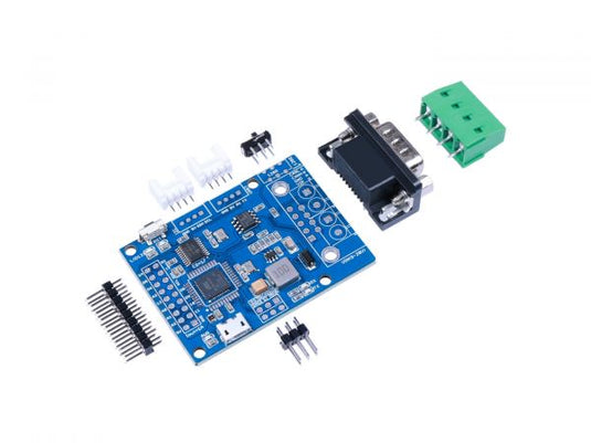
Part List

|
CANBed PCBA |
1 |
| sub-D connector | 1 |
| 4PIN Terminal | 1 |
| 4PIN 2.0 Connector | 2 |
| 9x2 2.54 Header | 1 |
| 3x2 2.54 Header | 1 |
LEARN AND DOCUMENTS
Documentations
Learn
 |
Introduction to CAN-BUS and How to use it with Arduino Ever heard of CAN-BUS but don’t exactly know what it does? Fret not! We will be discussing everything about CAN-BUS today. |
 |
CANBus Hacking for Beginners
This blog post highlights the available resources to safely play and hopefully learn more about CANbus and automobile/car hacking |