
Sinusoidal responses of series RLC Circuit | ThinkRobotics.in
The Series RLC circuit response, when it is powered with an AC source of sinusoidal nature.
Technically, the response or output we obtain from any electrical/electronics circuit after a certain period is called its STEADY STATE RESPONSE. Moreover, this response or behaviour of the circuit components remains the same as long as the source keeps supplying or there is no disturbing external force. It is the response of the circuit as time t tends to infinity, t-> ꚙ.
There is also a TRANSIENT RESPONSE, which is the response of the system immediately after the circuit forms a closed loop. After applying input, the output takes a specific time to reach a steady-state. This nothing but the Transient time and output during this time is Transient response.
In simple words, if the total circuit operation time is divided into six equal parts, then the transient response takes up the first part, and the steady-state response takes up the later five parts.
From an application and system stability point of view, STEADY STATE RESPONSE and its study play a vital role.
Steady State Response

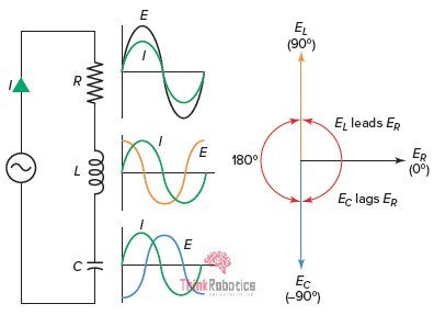
Fig 1: Series RLC circuit ; their waveforms ; Phasor diagram
Here, we will brief the Steady-state response of the series RLC circuit, as shown in Fig.1.
The circuit has RLC components in series with the voltage source. The current passing via all the passive components is (I) and is the same. Right next to every component is its waveform.
As we know, in the case of the ohmic component (resistor), the voltage (ER ) across it is in phase with the current (I) passing through it. Thus, in the phasor diagram, the voltage (ER) across the resistor is at 0 degrees, that when current (I) is considered to be the reference.
Next, the Inductive component (inductor) has voltage EL across it, and it LEADS the Current I by 90 degrees., ideally. Thus, EL LEADS ER BY 90 degrees.
Moreover, the Capacitive component (capacitor) has voltage EC across it, and it LAGS the Current I by 90 degrees, ideally. EC LAGS ER BY 90 degrees.
Note that this leading- lagging is considered with Current (I) at 0 degrees or reference.
The Impedance Triangle
Ideally, the phase difference between voltages of inductor-capacitor and that of the resistor is 90o but, that is not the case. Both the inductor and capacitor exhibit slight ohmic behaviour, expressed as Inductive Impedance (XL) and Capacitive Impedance (XC), respectively.
The Total Impedance of such an RLC circuit becomes:


Its Applications
- The fuses in our houses are nothing but very high capacity Resistors. Without them, it would be impossible to prevent any massive current/overload related damages.
- In capacitors, the impedance tends to control the flow of current in the electric circuit board.
- In Inductor, the impedance tends to control voltage in the electric circuit board.
- With the knowledge of XL & XC value, one can determine the Inductor and capacitor's voltages, respectively.
- And if we know phase angle (ɸ) along with it, then we can obtain the whole of the Phasor diagram.
- Phasors are a useful visualization of what's going on in an AC circuit. For example, we can realize sums and differences of waves (interference), vector sums and differences out of the rotating phasors and phase shifts between sinusoidal quantities.
- Both series and parallel resonant LC circuits are used in induction heating.
- It is also useful in the grounding of the generator/power transformer to dodge sudden fault currents.
- It is used to maintain a good voltage profile in long and medium distance power transmission capacitive and inductive compensation techniques.
- In the CFL bulbs, the RLC circuit is used to improve the lamp's operating power factor, thus reducing electricity consumption.
- Every device which uses a magnetic field for its operation is an RL circuit. The operation of these devices causes a voltage drop at its terminals due to the magnetic effect. To compensate for the voltage, drop a capacitor is used at its terminals. So, it's an RLC Circuit.
- Other than this, RLC circuits are used in the automobile ignition system to generate very high voltage with a mere 12V.
- The series RLC circuit mainly involves in signal processing and communication system. RLC circuits have a resonance, so they're useful for filtering out one frequency, or nulling out one frequency, or making a very stable oscillator, thus used in signal processing and communication system.
Sources:
- electronics-tutorials.ws/accircuits/series-circuit.html
- brighthubengineering.com/commercial-electrical-applications/47374-electrical-impedance-explained/#why-is-impedance-important
- quora.com/What-is-the-application-of-RLC-Circuit
- images.app.goo.gl/deEuNqNpzfLMwVNXA
- images.app.goo.gl/k5TH4wmwxb52JayL6